Suggested Technique for Using Centerlines and Construction Lines in Sketcher
Procedure
The following examples represent the concise dimension schemes and design intent that can be captured with the use of centerlines in Sketcher. Centerlines and construction lines can be used to control tangency and locate centers of arcs as well as aid in the sketching of other entities.
1. Centerlines 1 and 2, in Figure 1, are used to locate the centers of the smaller, tangent arcs at the endpoints of the larger arcs.
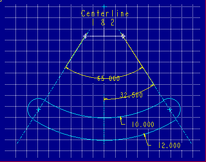
Figure 1
2. Centerlines 1 and 2 are also used to define tangency between the smaller arcs and the larger arcs. By creating centerlines which pass through the centers of both the smaller and larger arcs, tangency is ensured.
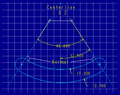
Figure 2
3. The vertical centerline, Centerline 3, is used to locate the centers of the two larger arcs horizontally. Centerline 3 is held in space from left to right by an assumption made by Sketcher at the intersection of centerlines 1 and 2 as shown in Figure 3.
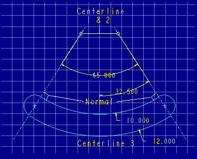
Figure 3
The above proceedure demonstrates the use of centerlines as a technique for locating centers of arcs and controlling tangency. The following demonstrates the use of construction lines.
Procedure
Construct a sketch, for a cut, with the given information:
- A pin is to fit into a groove.
- The groove is "V" shaped, however the dimensions of the "V" need to be controlled by the pin's diameter, not an angular dimension.
- The center of the pin must always remain aligned with the top surface of the cut.
1. Sketch the required "V" shape as centerlines. This shape is shown in Figure 1.
Figure 1
2. Create a construction circle using the selection 3 Points shown by Figure 2. Be sure to align the center of the circle to the top surface of the object.
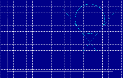
Figure 2
3. Add the "V" shaped sketched entities on top of the centerlines and dimension the sketch per the given constraints. Make sure to align the end points of the "V" shape groove to the edge of the model geometry. (Aligning in the default view is good Sketcher technique.) Figure 3 represents a proper dimensioning scheme.
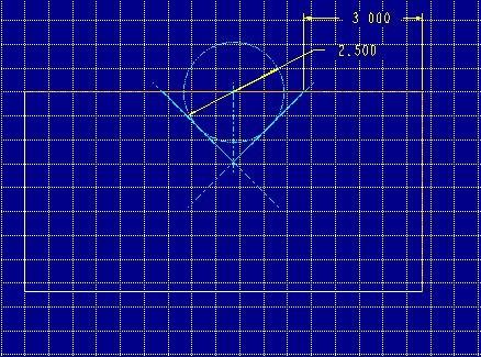
Figure 3
4. An Assembly relation between the diameter of the pin and the diameter of the construction circle will be used to drive the feature. Figure 4 represents the "V" groove in which the pin will be placed.
The angle and depth of the "V" groove cut can now be controlled by the diameter of the construction circle.
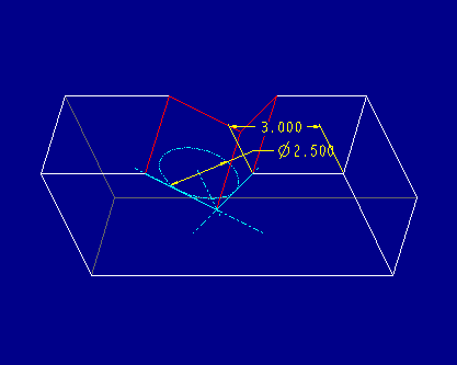
Figure 4
Please note that the examples above may not represent any particular design and are only shown for the intention of demonstrating good Sketcher techniques.
Back to Pro/ENGINEER technical information